PRODUCT OPTIONS
Available constructions and formats.
- Polyurethane polishing pads in different formats
- Custom diameter, groove pattern and backing options
- Pad supply for wafer, glass and ceramic applications

NWS-PAD · Contact materials
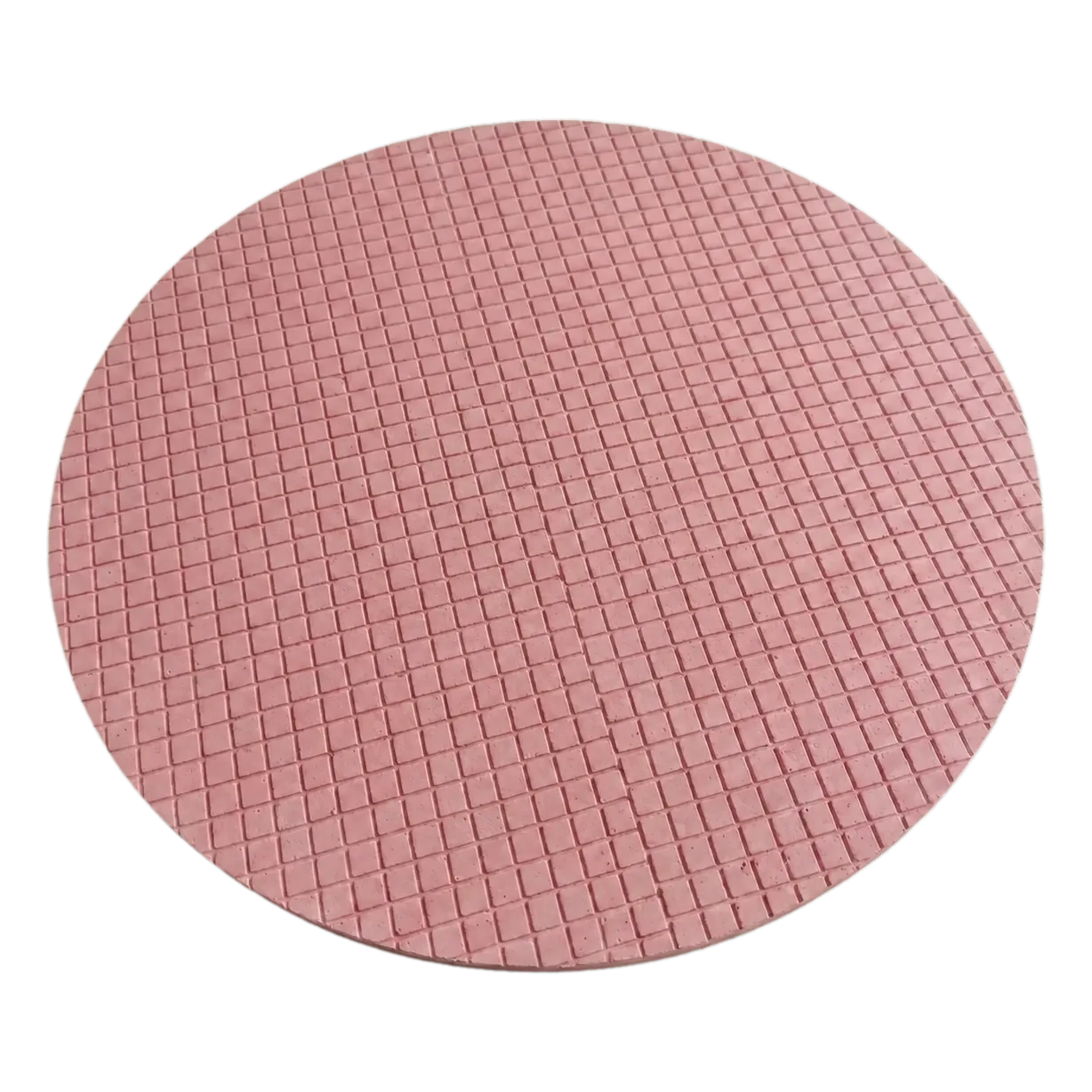
NEWWAYSMART · APPLICATION-SELECTED GRADES
Compare representative material and formulation options by workpiece and process stage. All products are made to order, with sample and first-article support. Numerical values below are typical selection references; the final specification is agreed for your process.
| Model / product | Workpiece & stage | Typical selection parameters |
|---|---|---|
| NWS-PAD-2101Ceria-Filled Optical Polishing PadsView grade → | Glass lenses and precision optical glassPolishing |
|
| NWS-PAD-2102Hard Pads for Sapphire and CeramicsView grade → | Sapphire, ceramics and metal partsGrinding / polishing |
|
| NWS-PAD-2201Nonwoven Substrate Lapping PadsView grade → | SiC, sapphire, microcrystalline glass and ceramicsCoarse / intermediate polishing |
|
| NWS-PAD-2202Microporous Damping-Cloth Finishing PadsView grade → | Wafers, optical components, glass and metalFine polishing |
|
| NWS-PAD-2203Zirconia-Filled Precision Optical PadsView grade → | Precision optical surfacesPolishing |
|
| NWS-PAD-2301Foamed PU Pads for Glass WafersView grade → | Microcrystalline glass, glass wafers and prismsPolishing |
|
| NWS-PAD-2302Nonwoven Wafer Pre-Polishing PadsView grade → | SiC, GaAs, silicon, sapphire and metalInitial polishing |
|
| NWS-PAD-2303Compliant Final-Polishing ClothView grade → | SiC, GaAs, silicon, sapphire and glassFinal polishing |
|
| NWS-PAD-2401Fixed-Diamond Pads for Hard SubstratesView grade → | Glass, microcrystalline glass, sapphire and ceramicsFixed-abrasive grinding |
|
| NWS-PAD-2501Synthetic-Fibre Pads for Wafer LappingView grade → | SiC, GaN, GaAs, InP, silicon and optical glassLapping / polishing |
|
Need a different size, hardness, particle distribution or chemistry? Send your current process and target. For slurries, particle size is only labelled D50 where that statistic is specified. Shore A and Shore D hardness values are different scales.
PRODUCT OPTIONS
CUSTOM SUPPLY
APPLICATIONS
APPLICATION & ORDER INFORMATION
Custom dimensions and configurations are available. Send a drawing, sample photo or product requirement for an order-specific quotation.
Material, dimensions, configuration and order quantity affect the quotation. We do not publish a universal price for custom products. Request a quotation for your product →
PRODUCT TYPES
EXPLORE NEWWAYSMART
RELATED PRODUCTS
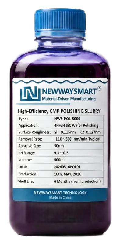 Slurries, Compounds & AbrasivesFormulation-led polishing media matched to substrate, contact tool, delivery mode and target surface.
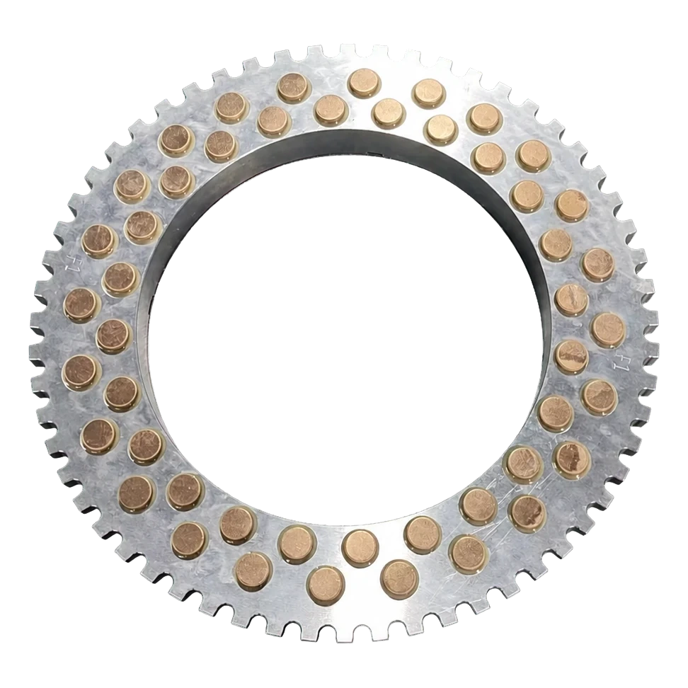 Conditioning Rings & WheelsDrawing-based tools for plate correction, surface renewal and repeatable working-face preparation.
 Adsorption & Holding PadsWaxless holding directions for stable location, protected contact and controlled release during processing.
DRAWING · SAMPLE · PRODUCT REQUIREMENT