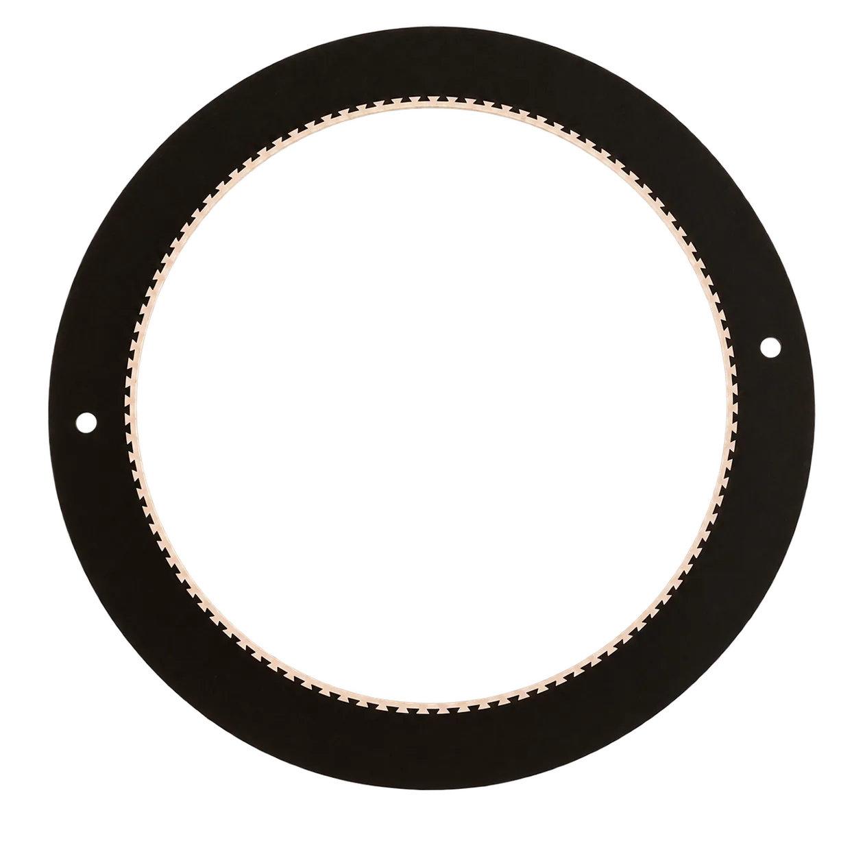
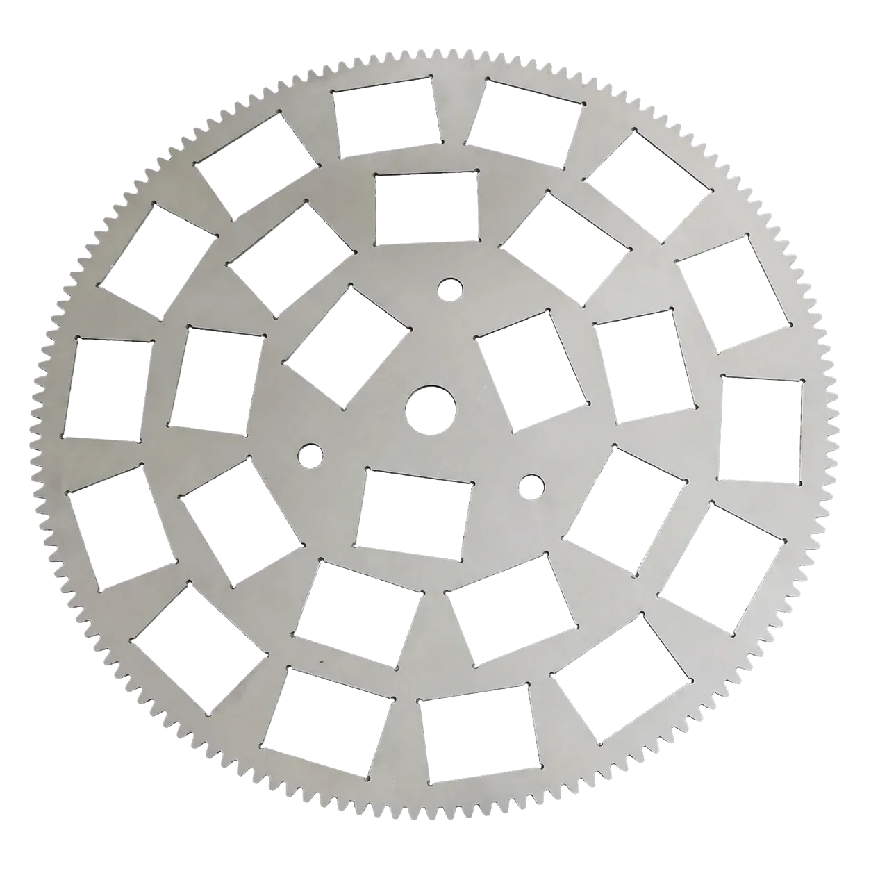
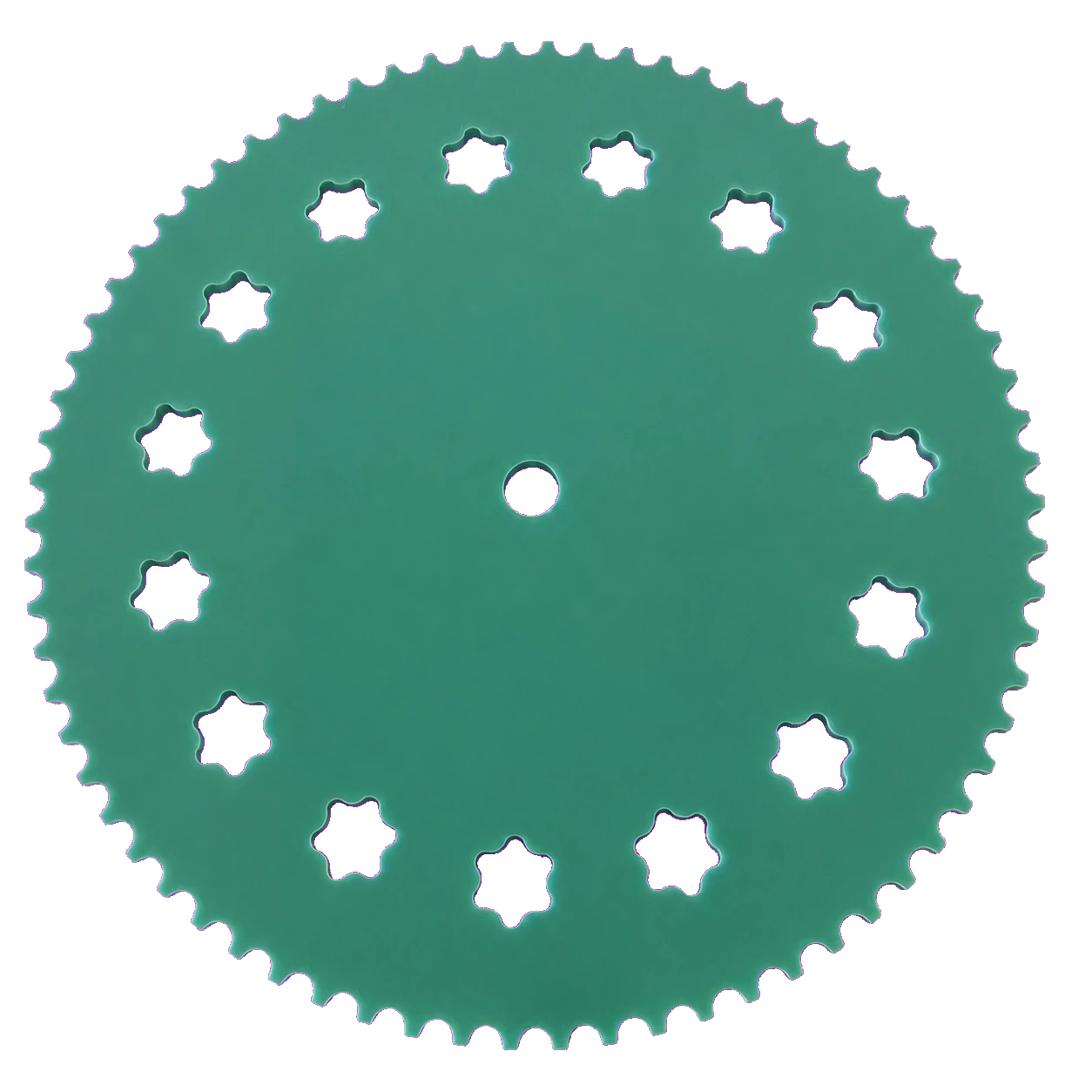
Composite carrier

Composite Lapping Carriers

A precision metal drive body with engineered polymer contact zones for sensitive, brittle or high-value workpieces.
Composite Lapping Carriers

WHY THIS ROUTE

Designed around the complete process interface.

  • Metal strength at the machine drive interface
  • Polymer contact selected around marking, chipping and chemistry
  • Pocket geometry, retention and clearance developed from the drawing

FIRST REVIEW

Information that moves engineering forward.

  • Machine and inner/outer gear data
  • Workpiece material, size and finished thickness
  • Wet chemistry, pressure and speed
  • Contact marks, edge damage, wear or release concern

APPLICATION FIT

Typical directions to explore.

  • Semiconductor substrates
  • Precision glass and optics
  • Technical ceramics

PRODUCT FAMILY STORY

Custom-made around the job—not selected from a fixed shelf.

A composite carrier is developed as one controlled assembly: the metal body carries the machine-drive duty while engineered contact zones address the workpiece interface. Geometry, insert retention and wet-process compatibility are reviewed together rather than purchased as separate promises.

Within this family

  • Metal-body carriers with polymer pocket contact
  • Replaceable or integrated contact-zone concepts
  • Round, rectangular and application-shaped pockets
  • Single- and double-side machine directions

Design focus

  • Drive-body stiffness and edge-tooth engagement
  • Pocket clearance and protected contact
  • Insert geometry, retention and traceability
  • Chemistry, wear and cleaning compatibility
Composite Lapping Carriers product family reference
Product-family reference
Lapping & Grinding Plates connected process tooling
Connected process interface

VALIDATION & RESULT FOCUS

Build evidence before making a production promise.

Every application is reviewed against its own machine, material, process and acceptance method. These are the evidence points normally carried into the next decision.
  1. 01Measured first-article geometry
  2. 02Workpiece-edge and contact review
  3. 03Approved revision for repeat supply

ENGINEERING DEFINITION

Four connected decisions before a repeatable product.

01

Define the machine interface

Confirm plate size, carrier OD, inner and outer gearing, tooth data, motion, load and liquid delivery.
02

Protect the workpiece

Review workpiece material, pocket shape, clearance, thickness, orientation and every possible edge-contact point.
03

Match material and chemistry

Connect strength, wear, acid/alkali resistance, corrosion, metal-ion risk, slurry and cleaning requirements.
04

Validate the route

Agree first-article measurements, acceptance evidence, change control and the path toward repeat supply.

DRAWING & DESIGN INPUTS

What the product page cannot safely assume.

These fields turn a general product enquiry into a controlled engineering review. Share what is available; missing inputs can be structured together.
Geometry
OD, tooth count, module or DP, pitch circle, pocket geometry, thickness and datum
Workpiece
Material, size, finished thickness, quantity, orientation and protected surfaces
Process
Single- or double-side route, speed, pressure, slurry, temperature and cleaning sequence
Acceptance
Flatness, parallelism, TTV, finish, edge condition, contamination and service-life method

ENGINEERING & KNOWLEDGE ROUTES

Continue from product choice to the relevant review.

Application engineering Custom engineering Validation & repeat supply Technical knowledge

PRODUCT REVIEW FAQ

Useful answers before sending the first drawing.

Is a drawing required?+

A controlled drawing is the fastest route. If none exists, share the sample, machine and gear data, workpiece dimensions and process target so a reviewable design direction can be prepared.

How is carrier pocket clearance defined?+

It is application-specific. A +0.2–0.3 mm diametral allowance is a common discussion starting point, then material, loading, liquid film, temperature and edge risk determine the final drawing.

Can material be recommended?+

Yes. Blue steel, stainless steel, resin, engineering plastic and composite-insert directions are compared against stiffness, wear, chemistry, contamination and contact protection.

What confirms production readiness?+

The agreed drawing, measured first article, application trial and acceptance method form the release baseline. Final feasibility remains process- and validation-specific.

FROM REQUIREMENT TO REPEAT SUPPLY

Bring the drawing, the process constraint and the target result into one review.

Prepare the first review →