Cutting-insert carrier · Epoxy & Resin Carriers

V-Style Insert Lapping Carriers

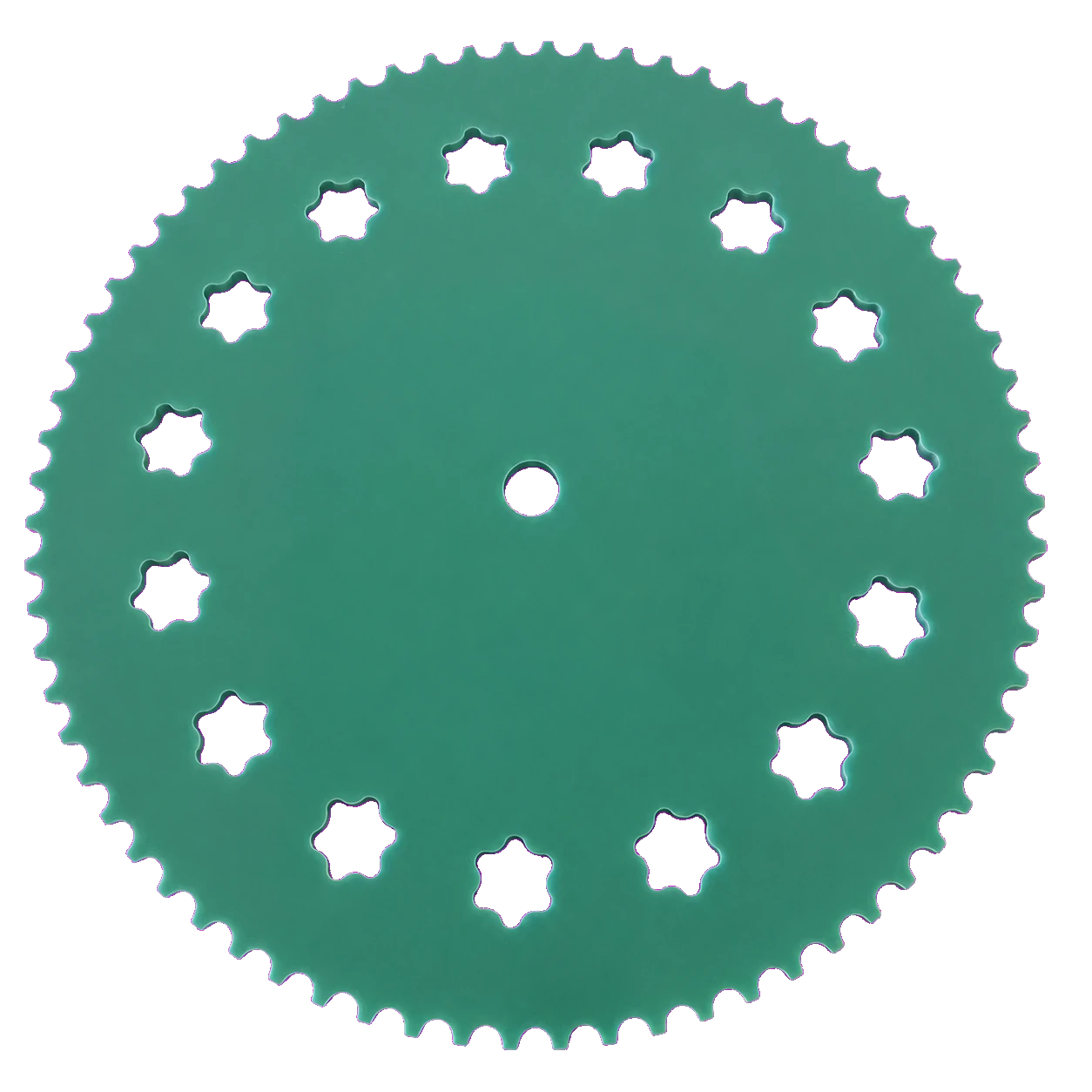
Protected pocket and loading directions for VNMG and related 35-degree rhombic insert families.
Epoxy & Resin Carriers family reference; not the exact V-Style Insert Lapping Carriers configuration
Product-family reference. Geometry and materials are defined for the order.

HOW THIS PRODUCT IS JUDGED

Connect the physical product to its process function.

V-style inserts concentrate risk at two acute tips. Pocket relief, loading sequence and workpiece rotation are therefore explicit drawing features.

PRODUCT IDENTITY & CONFIGURATION

NWS-PLC-INS-V

PLC = polymer carrier; INS = cutting insert; V = 35-degree rhombic workpiece familyA physical sample is preferred when the full insert suffix and maker drawing are unavailable.
VNMG160408V13
Workpiece familyconfirmed
V-style 35° rhombic indexable inserts
Critical geometryverify
Acute tips, pocket corner relief and loading direction
Pocket populationverify
Balanced around the carrier path after bridge and collision review
Inspectionverify
Pocket profile, position, burr/edge condition, carrier thickness and flatness
  1. 01Confirm the insert drawing, physical sample and the ISO designation independently.
  2. 02Derive the carrier pocket from the controlled insert outline; clearance is a project variable, not a fixed catalogue value.
  3. 03Add the external tooth form only after machine plate, sun gear and ring gear data are checked.
  4. 04Set carrier thickness from the workpiece and process stack, then release a first-article drawing for approval.

SELECTION FOCUS

Questions that change the direction.

  • 35-degree tip geometry
  • Insert face and orientation
  • Allowed edge contact and release method

RFQ & DRAWING FIELDS

Evidence needed before release.

  • Insert drawing or measured sample
  • Pocket corner relief and position
  • Carrier thickness and material
  • Machine teeth and first-article check

PRODUCT REFERENCE

Confirm the configuration for your part.

Loaded and empty views, 35-degree tip clearance macro, side thickness, tooth profile and protected packaging.Do not submit confidential customer drawings until a secure project channel is confirmed.

PUBLIC CLAIM BOUNDARY

Typical direction is not a performance guarantee.

Dimensions, materials, removal rate, roughness, life and compatibility are published only when supported by an approved drawing, material record or project-specific validation. Unverified label examples, third-party photographs and customer pricing remain internal references.

RELATED TYPES IN EPOXY & RESIN CARRIERS

Compare neighbouring constructions.

Laminate carrierG10 / FR4 Laminate CarriersMachined laminate carrier directions for protected contact and economical process development where their stiffness and chemistry fit.Engineering polymerPEEK, PI, PPS & PEI Carrier DirectionsEngineering-polymer carrier directions screened around temperature, chemistry, stiffness, wear and workpiece contact.Polymer carrierPOM, PA, PVC & Cast-Polymer CarriersApplication-led polymer workholding for contact-sensitive parts and defined chemical environments.Cutting-insert carrierC-Style Insert Lapping CarriersDrawing-controlled epoxy or laminate carriers for CNMG, CCMT and related 80-degree rhombic insert families.

DRAWING · SAMPLE · PROCESS EVIDENCE

Start with what is known. Keep assumptions visible.

Prepare the first review →